 Blog RSS Feed
 Via E-mail
 Twitter
 Facebook
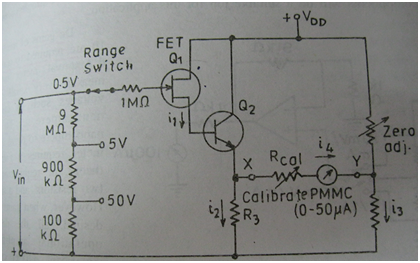
| In this article I have explained the working and construction of a direct coupled amplified DC voltmeter with its circuit diagram using operational amplifier and working of FET as input amplifier for the DC measurement. | ||||
Direct coupling amplifier in DC VoltmeterHere in DC voltmeter we apply a series of resistors and MOSFET for the purpose of amplification of input applied signal or the test input DC voltage that may have very less amount of power for the derivation of moving pointer. On the general basis a DC meter movement (referred by PMMC) is evolved in it along with the DC amplifier as has been, already, discussed here and which can be a single or multi-stage. It is to be emphasized that the used of FET is driven by the situation when input resistance used in amplifier stage is of very high value because only a small amount of input current id required for working of FET. In spite of use of FET in the circuit some stage may involve a transistor and in that case the input to the transistor can directly be fed from that of FET. These type of direct coupled amplifiers are usually found in those DC voltmeter having relatively low price. Here in the following figure it is shown that a FET is used for the purpose of directly coupling amplification of input signal where as a bipolar transistor makes a balanced bridge circuit by the use of several resistors with it. In this circuit function of FET is to serve as a source follower and it transforms the impedance between input section and base terminal of the transistor used. Circuitry of direct coupled DC voltmeterThe bipolar transistor is provided with the DC biasing so that when Vin equals to zero then we may get i2=i3. This condition yields the result vx=vy Which results in zero current flow through meter movement which means i4=0. The biasing of base of transistor is controlled by the input voltage Vin. In this way upon application of input voltage to the circuit it results in increase of base bias voltage of bipolar transistor that further makes vx to rise. Now as vx has increase so it becomes greater than that of vy, thus i4 becomes a non-zero quantity i.e. i4 is not equal to zero. In this way quantity of this current, generated, and deflection of meter becomes proportional to that of input applied voltage Vin. Here we talk about that applied input voltage that corresponds to the maximum meter deflection this deflection is called range of the instrument. This is usually called the lowest range on range switch in state of non-amplified model. Whereas the highest range can be obtained attenuator at input section and lower by input pre-amplifier. Panel controlled is made to calibrate the input attenuator as is also shown in the figure and this is done with help of resistor voltage divider. Full scale voltage appears across the this resistor divider so that voltage at each terminal(tape) is a progressively lower fraction of input voltage. 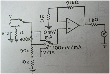 Circuitry for operational amplifier based DC voltmeterThe zero set potentiometer is used the adjustment of bridge balance point. What are the advantages of direct coupled amplified DC voltmeter?One more circuit diagram can be used for illustrating the working of a system of a meter used for measurement of small voltage and current. Where the input voltage is first amplified and then applied to the meter. Now taking a case when amplifier has a gain of 10 then the sensitivity of the system will also increase in the same way in its accordance. Now a DC coupled amplifier having an amplifier that do not use any coupling capacitor and also consists of a well controlled DC gain. This whole system, when put along, gives the required amplification. It is not difficult to make an amplifier with a fixed DC gain of 10 but it can also be made to work in the same state for continuous basis of time. This job can be done satisfactorily by applying an operational amplifier along with a required feedback component. The gain of DC voltage more than 10 is required for the movement of D'Arsonval meter movement along with the voltage in range of micro volts and nano-ampere. A gain of ten to the power 6 is required for the satisfactory driving of a mili-ammeter. For this function to be done it requires the following things given below: • An operational amplifier • Two resistors • And a simple circuit When gain of DC voltage of this much high order is requires then all the defects of used operational amplifier are to be considered. The parameters like: • Offset current • Offset voltage • Bias current These factors become so vast trouble causing problems that practical possibility of construction of such a amplifie r from a given operational amplifier becomes diminished. But some of the problem encountered in this way can be removed when the use of trim adjustable accessible is made from front panel. This is done in the same way as is calibrations zero functioning is set. There are some factors like temperature and time induced drift kames the amplifier to become unstable. In this way after the amplifier becomes unstable it is required to reset the amplifier again. When we discuss about those direct coupled amplifiers that are optimized for following factors: • Low temperature drift • Low offset • Low bias current These are called instrumentation amplifiers. These are made by semiconductor suppliers in the industries. | ||||


0 komentar:
Posting Komentar